Bullet Designs

|
|
Semi-Wadcutters
Bullet jacket lengths are relative to the lead coverage on typical pistol bullets. The full jacket is made for ogival-type bullets (no shoulder). When used for a semi-wadcutter style, the full jacket makes only the heaviest weights. The 3/4-jacket covers nearly the entire shank, leaving the nose exposed. It makes a medium to light weight ogival bullet (no shoulder), but a normal (medium) weight semi-wadcutter. The 1/2-jacket covers about half the normal weight bullet's shank. It can also make 3/4-jacket style (shank covered) in the light weights. A gas check only covers the base and a small portion of the shank. A Base Guard covers only the base but scrapes fouling out as it passes the sharp edge down the bore.
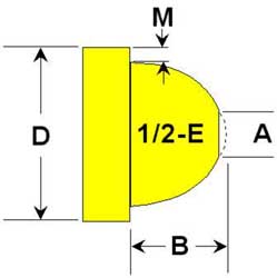
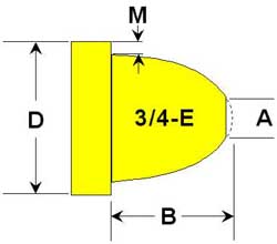
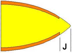
3/4-E Semi-Wadcutter (SWC) bullets are illustrated, using the same weight of core for all jackets.
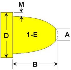
Compare these 1-E (one caliber, elliptical curve) ogive bullets with the 3/4-E. The typical handgun bullet weight and length generally works best with a 3/4-E ogive. The 1-E looks good on paper, but usually results in far too much volume of lead in the nose, making the bullet either too heavy, or nose heavy, in pistol weights. In rifle length bullets, the longer (1 caliber length along the axis) nose is a good match to the design. For some special purpose handgun loads, the 1-E can be satisfactory (usually only for the heaviest bullet weights).
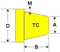
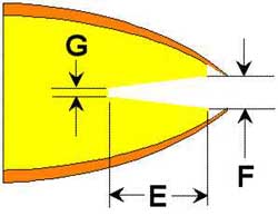
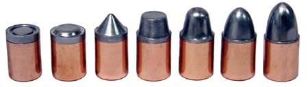
These Keith (named after the late Elmer Keith) or Truncated Conical Semi-Wadcutter style bullets are shown with the same weight, using different jackets. These are the so-called "Full", "3/4", and "1/2" jackets, then the gas check and Base Guard. Of these styles, the full jacket will usually be too heavy, and the 1/2-jacket and gas check may tend toward lead fouling. The Base Guard tends to scrape out the fouling for a cleaner bore, up to about 1200 to 1400 fps, in most guns, provided the diameter is a good fit to the bore.
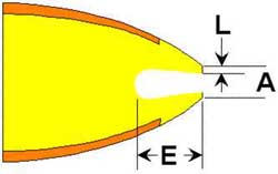
These Keith Semi-Wadcutter style bullets are shown with the minimum practical weight for each jacket style. The minimum possible in a SWC design is where the lead just stops at the edge of the jacket, with the nose projecting. If the punch is driven down further, it simply crushes the jacket. To make lighter bullets in a simple SWC type die, you can use these techniques:
- Use a deep hollow point punch to remove some weight at the nose.
- Use a cup base punch to remove some weight at the base.
- Use a core material of low density, such as Corbin's polymer "bullet balls".
- Use a mixture of low and high density materials in the same bullet.
- Use powdered copper/tin mixture for the core instead of lead.
- Use a shorter nose design (minimum is a large HP with no nose projecting).
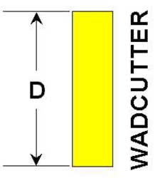
Button nose wadcutters (BWC) are classified in our system as another form of SWC design. Wadcutters simply have less nose (or no nose) projecting from the end. They still have lead just at the edge of the jacket, if one is used, and are made in the same die as a SWC, by changing to the proper nose punch. A TWC (target wadcutter) does not have the tiny "button" of lead for a nose, and is flat across the end. It has a small ring depressed into the face, like a target. The wadcutter designs are the minimum weight in the jacket without going to a hollow point or cup base design. Note that a cup base generally does not work on a gas check, and never works on a Base Guard because of the method of attaching the copper disk.
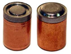
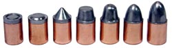 Semi-wadcutter nose shapes (standard) from left to right: Target Wadcutter (TWC), Button Nose Wadcutter (BWC), Conical, Keith, Auto-Loader (AL), 3/4-E, 1-E. (Click the picture for a larger image). Photo by D.R. Corbin, of .452 Bullets.
|
|
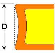
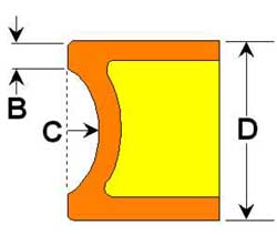
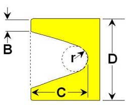
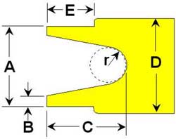
Semi-Wadcutter Shapes
Wadcutter Shapes
Button Nose has a slight nose, Target Wadcutter has a depressed ring and is flat across.
To design a special semi-wadcutter style bullet, print one of the diagrams listed below, and put in the dimensions you desire. Then send us a copy.
In order to make the bullet, we must machine a punch with the reverse shape in the tip. Some designs can be too fragile or nearly impossible to machine. Others may have difficulty with trapped air or lube, or may not release the bullet nose easily enough. We can help sort out these problem areas in designs, and suggest changes that would solve them while accomplishing whatever it is you want the bullet to do.
|
Bullet Bases
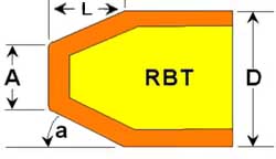
Bullet Bases can be made in the flat (FB), dish base (DB), cup base (CB), hollow base (HB), heel base (no abbreviation used), boattail (BT), and the superior rebated boattail (RBT). Corbin does not make the standard BT but only the RBT, which offers about 15% better accuracy due to less muzzle blast induced dispersion, better barrel life, less gas cutting in some loads, and far longer tooling life.
-
 The dish base (DB) design is generally used to provide a very slight outward expansion of the bullet during firing, by vectoring a small component of the gas pressure at a slight angle to the bullet centerline. This can help "seal" the bore when the bullet is used in undersize or unknown size barrels and prevent gas cutting. It seems to have little or no effect on accuracy other than improving it in an oversize barrel. It can also be used in a rimfire 6mm jacket to help apply more localized pressure, during core seating, to the edge of the jacket and thus expand it better, removing as much of the prior firing pin dent as possible. Dish base bullets have a slight concavity, going from edge to edge without a margin, and typically using a radius of several times the diameter to produce a very shallow curve, usually less than 1/10 of the caliber.
-
 The cup base (CB) is typical of paper-patched lead bullets, but can also be used with a jacketed bullet. It has a radius cavity that is less than half a caliber deep, starting after a margin of from .010 to 0.030 inches (typically about 0.020) from the edge of the bullet. The margin gives the bullet edge greater resistance to expansion at the muzzle, and is designed for the range of muzzle pressure expected. Thicker margins work best with short barrels and high pressure loads, thin margins work best with longer barrels and lower pressures. The problem with a very thin margin and a high pressure at the muzzle is that at the moment the barrel is "uncorked" by the bullet passing the muzzle, the pressure is supported momentarily only by the thin walls of the bullet base. The pressure can expand the base excessively, even to the point of cracking it apart.
However, with proper margins, the cup base allows even expansion of a section of the bullet shank near the base, sealing the bore and providing a good grip on the rifling. It also moves the weight slightly ahead on the bullet, to compensate for potentially too slow twist rates for the bullet length and increase stability. Stability in a bullet is desirable to a point, but if the weight is shifted far enough toward the front, then the bullet wants to maintain its launch attitude or angle all the way to the target instead of turning to follow the trajectory arc. The balance between how much stability to use in overcoming potential twist rate issues for ultra light or ultra long bullets, and how much instability to allow so that the rifling spin can keep the nose following the trajectory arc, is a matter of experimentation.
-
 The hollow base (HB) bullet typically has a conical or combination radius and conical cavity shape, but it may be made with a truncated conical cavity. The difference between hollow and cup base is the depth. Hollow bases are almost always made a half caliber or deeper. This shifts the weight considerably forward on the bullet. Hollow bases are generally impractical to use with jacketed bullets, as the jacket will be penetrated and cracked by the amount of force needed to draw it into this conical shape in a simple one stroke operation. The HB shape is typically used on lead handgun bullets, or on large calibers where the weight would be excessive if the bullet were very long with a solid base. Shotgun slugs, airgun pellets, and other projectiles that need to conform to the bore easily, or need to have the stability guaranteed over a moderate to short range, often are made in a hollow base design.
-
 The heel base bullet is made to fit into the cartridge case up to the base shoulder, and is used in certain very old calibers where the original size of the bullet diameter was the same as the chamber. Conversions of blackpowder cap and ball revolvers to shoot cartridges meant that the chambers usually fitted the ball or bullet diameter, so inserting a cartridge meant the cartridge case diameter needed to be the same. Later, when guns were manufactured as cartridge revolvers, rather than using existing cylinders or stock tooling and supplies originally designed for cap and ball guns, the cases were made larger than the bullet diameter so that the bullet lubricant grooves would be inside the case, protected from dirt.
We have the .38 caliber revolver cartridge that is really a .357 diameter, because of this hold-over designation from the old heel-based bullet days. The 38-40 actually uses a .40 caliber bullet. Nearly every .38 made today uses the same diameter bullet as the .357 Magnum with some exceptions. A heel based bullet is used in the .22 rimfire cases even today, with lubrication on the outside of the cartridge (but a dry lubricant that doesn't pick up dirt is normally used).
-
 Boattail base (BT) bullet dies are not made by Corbin for a number of technical reasons, primarily that there is no point in making something that isn't as good as the RBT design has proven itself to be over the decades. But most mass produced bullets including military designs still use the old boattailed design, as it is easier to keep on doing it than to convince people there is anything better (and, the tooling is paid for, the advertising has been written for years, and there is no upside to the manufacturer so long as no one else does it either).
Boattail bullets have a tapered base that helps smooth the passage of air over the base and reduces base drag. This is true at any speed, but it has a small fraction of the total drag at supersonic speeds. The nose drag becomes so much greater that the base effect is largely buried in the improvements that a nose design can make. At subsonic speeds, the reverse is true. A blunt bullet can be made to fly further and with less drop below the speed of sound if the base is streamlined, compared to making the nose more pointed.
-
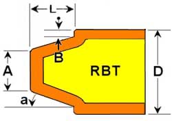 Rebated Boattail (RBT) bullets were first introduced in mass production by the Finnish Ammunition concern of Lapua (controlled by the Finnish government). The design provided a solution to the problem of muzzle gas focusing itself in a ball in front of the emerging bullet, which takes place with a boattail design. Flat bases, and rebated boattail, deflect the laminar flow of muzzle gas that wishes to follow the smooth outline of the bullet and then break up right in front of it. The gas is forced to flow off in a ring, with a clear area in the center through which the bullet passes. This can make up to 15% improvement in the dispersion or group size.
The RBT is made in two steps. With standard drawn flat base jackets, the base is first formed into a boattail shape without a step, using the BT-1 forming die. To do this, the lead core is seated into the jacket while the jacket is in this boattail shaped die. The lead pressure forces the jacket to take on the boattailed shape.
Then, the bullet is moved to the BT-2 finishing die. This die has a slightly different angle than the first one, and a sharp shoulder between the boattail angle and the shank. The edge of the bullet easily slips past the shoulder with no pressure applied. Then, the lead is compressed with the same external core seating punch that was used in the BT-1 die. The pressure of the lead inside the jacket causes the jacket to push out against the die wall and take on the RBT shape.
When the bullet ogive is formed, a hollow cavity type of external punch cradles and supports the RBT base, and gives it the final definition and edge sharpness. The RBT edge is somewhat rounded in the prior stage, and receives its final form during nose forming in the "PF-1" point form die. The RBT punch edge is usually 0.010 to 0.025 inches wide depending on the caliber, jacket wall, and physical strength required to support the pressure.
-
 The flat base (FB) is, of course, the most common and is the "default" design when no other design is mentioned for a jacketed bullet. With a lead bullet, the Base Guard (BG) and the flat base (FB) are ballistically identical: they perform the same way and you can use a BG punch without the copper disk with no ill effect (a tiny bump appears in the exact center of the base). However, the BG design will scrape fouling from the bore, whereas an ordinary flat base lead bullet has no capability to do this. A gas checked base is less effective at cleaning the bore than the BG base.
|
Rifle Nose Shapes
-
 Spitzers or "tangential ogive" bullets are a special case of secant ogives where the angle joining the nose and the shank is zero. That is, all bullet noses that utilize a section or arc from a circle as the major shape of the ogive are secants, but we reserve the tangent or spitzer name for the one special case of zero angle of junction.
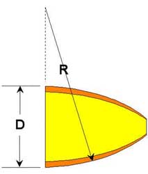
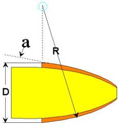
The spitzer bullet is constructed on paper by drawing two arcs with a compass, the radius of each being identical, and being specified in "calibers". The two arcs are drawn so that they start at the shank and curve toward the center line of the bullet, crossing or at least touching the center line. The origin of the radius is located on a line perpindicular to the centerline and even with the end of the shank.
 A spitzer is designated in calibers of radius, such as 2-S, 6-S, or 10-S. This means that the length of the radius of the ogive arc is 2 calibers, 6 calibers, or 10 calibers. Since the arc has to go from the shank to the centerline, it isn't possible to make a spitzer with less than 0.5 caliber radius (which is a round ball nose and is identical to a 1/2-E eliptical ogive).
Tangential ogives are the most popular and common shape, and they are mathmatically easy to describe and to create on paper. The one thing people often forget is the jacket thickness, which prevents the tip of the bullet from being closed to a sharp point. If the jacket has .035 inch thick walls, then the absolute minimum tip closure will be 0.070 inches across, and more likely it will be 0.091 to 0.105 inches because of the pressure that smaller closure would require and the strength of the ejection pin needed to push the bullet back out of the die.
 Most rifle bullets use a 6-S ogive because it gives the best range of weight to length, until the caliber becomes large enough to make the weight excessive. Usually a 4-S or shorter radius is used for calibers of .375 and larger, until we get to the very large and heavy .512 (50 Browning Machine Gun) bullet, which is used in guns that can handle 600-900 grain bullets. This lets us use a longer ogive radius again, from 6-S to 10-S being typical.
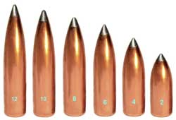 The larger the ogive number for a spitzer, the more pointed the bullet becomes. It also becomes longer in a non-linear manner. The greatest changes in length take place in the low end, and become less and less as the same amount of change takes place in larger numbers. That is, a bullet that goes from 2-S to 4-S becomes significantly longer and more pointed. Going from 4-S to 6-S makes a noticable but smaller difference. From 6-S to 8-S is a moderate change, and from 8-S to 10-S is less so. But from 10-S to 12-S, you can barely tell the difference, and for longer ogives, the only noticable difference is at the very tip, and only if the meplat or end is very sharp.
Corbin offers spitzers in 6-S for most calibers as standard. Ogives of .5, 1, 2, 4, 6, 8, 10, and 12 can also be made, and for longer ogive, we recommend the ULD or 14-caliber secant with a 0.014 offset from tangent.
-
 Secant ogives are just like tangents except the junction of the ogive and shank makes an angle other than zero. Therefore, it is not enough to specify the secant ogive radius in calibers. You must also define either the angle of attachment, or the distance that the ogive would have to be moved sideways in order to make it meet tangent with the shank.
A secant ogive has a bit of a discontinuity or non-smooth change from ogive curve to shank. The idea is to join a long ogive radius to the shank so that the axial length (along the centerline) can be made shorter than if the entire arc from tip to shank were joined tangent to the shank. We "slide the ogive" over to one side and chop off a bit of the curve, in other words.
 The reason for doing this is to try to fool Mother Nature into thinking that there is a smooth ogive, without any discontinuity, and get a more streamlined curve that isn't so long as it would be in a spitzer. That makes the bullet closer to a practical weight, because the over-all length is shorter. A 14-S secant with .014 offset can be as short as a 10-S tangent, depending on the relative size of the meplats. If the angle is increased enough, the secant starts to generate a secondary shock wave from the disrupted air flow, and the advantage of having a longer ogive curve is lost. There is a narrow practical range where a secant works well for supersonic bullets, and not much reason to use it at all for subsonic bullets.
 Pushing the design to the edge of practicality is a mistake in most cases, if you are not positive about the atmospheric pressure and humidity at the time of firing and design for it. A bullet that is optimized for low drag at normal air density may develop a secondary shock wave if the density increases slightly, spoiling any plans to get lower drag than a more normal bullet design. Worse, the conditions might be "on the edge" of switching back and forth, where a tiny change in pressure generates a shock wave from the ogive-shank junction over just part of the flight, depending on velocity as well as shifts in weather, and your groups go all over the target.
Better to sacrifice a little "paper advantage" and work well within the area where such small changes in conditions would have no effect.
Pushing the design to the edge of practicality is a mistake in most cases, if you are not positive about the atmospheric pressure and humidity at the time of firing and design for it. A bullet that is optimized for low drag at normal air density may develop a secondary shock wave if the density increases slightly, spoiling any plans to get lower drag than a more normal bullet design. Worse, the conditions might be "on the edge" of switching back and forth, where a tiny change in pressure generates a shock wave from the ogive-shank junction over just part of the flight, depending on velocity as well as shifts in weather, and your groups go all over the target.
Better to sacrifice a little "paper advantage" and work well within the area where such small changes in conditions would have no effect.
-
 Eliptical ogives have a constantly changing radius about two loci or focal points, so you can't specify them with a single ogive radius figure. The best way to describe them quickly and positively is by the axial length, or distance in calibers they extend above the shank along the center line of the bullet.
However, this method means you have to be aware that the changes in length are huge when you go from a 1 to a 2 caliber. The smallest possible eliptical ogive is 1/2 or 0.5-E. That is a circle or ball, because the length of the nose is half the caliber, or the exact radius of the bullet. Going up to a 3/4 or .75-E nose gives us the typical round nose handgun bullet, which is not really "round" but is "half a prolate spheroid". This jargon means you could form a ball, squash it so that it looks a little like a round-tipped football (prolate as opposed to the other direction which is doughnut-like oblate), and cut it in in half at the middle, so you have half of the football, a kind of rounded-end cone.
 A 1-E ogive is a full caliber long in the nose. If you had a 1-inch diameter shell, the nose would be 1 inch long, same as the caliber. In contrast, if you changed the shape to 3/4-E it would only be 0.75 inches long, and 1/2-E would only be 0.5 inches long. Some people want to make a 2-E ogive, but if you draw it out to scale you soon realize that this is a bullet that is all nose in any practical weight for small arms ammo. For instance, a .458 rifle bullet with a 2-E nose has a nose that is 0.916-inches long! To be reasonably balanced, the nose and base need to be somewhat in the same general length range, and certainly more than a caliber for the shank alone. You'd have over 1.83 inch long bullets in .458, for instance. Want to shoot a 650-700 grain .458 from your favorite .45-70 rifle? Will it even feed or chamber?
The 1-E ogive is very much a standard for black powder cartridge rifles, paper patch bullets, and modern big game jacketed bullets used in Africa. It is a good shape for hunting, although not particularly aerodynamic for long range shooting. The 3/4-E is standard for handgun, and the 1-E is standard for rifle, but other shapes of eliptical ogives can be made to custom order.
-
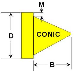
 Spire point bullets are made with two straight lines, joined to the shank at a specified angle (which is typically 9 to 12 degrees). The spire shape is like a pencil tip or "church spire" in shape. Do not confuse spire and spitzer. The spitzer is a curve, an arc from a circle. The only curve in a spire is a possible tiny radius joining the shank to the ogive, which is probably incidental to the polishing process and not by design.
Spire point bullets are ballistically equivalent to spitzers of the same axial ogive length. They take a straighter path from shank to tip, and cut off a small amount of volume by doing so. Therefore, a spire point bullet can be slightly lighter for the same over-all length. There is no particular disadvantage other than the need to maintain a smaller angle of tip for bullets that will be shot at supersonic speeds, to avoid generating a secondary shock wave at the ogive-shank junction.
|
Bullet Tip Styles
-
 The Open Tip (OT) is just the result of seating the core below the jacket. This is sometimes called a hollow point but that is not the correct name for it. You can have an open tip with a hollow point, a lead tip with a hollow point, an open tip without a hollow point, or a lead tip without a hollow point. But you can not have a lead tip with an open tip. This is a contradiction.
In order to make an open tip bullet, you need a core seating punch that fits the ID of the particular jacket you plan to use, at the distance from the mouth where the lead will finally be compressed. Fortunately, you will be able to use a punch that is one or two thousandths of an inch smaller than "perfect fit" because you do want air to get round the punch and escape, and you don't want to dig into the jacket wall during seating.
This means that a jacket with .035 walls takes .070 inches away from the caliber, so if you had a .308 bullet, the jacket would probably be .306 before you seated the core (jackets expand during core seating to nearly finished size). Taking .070 away from .306, you have an inside diameter of 0.236 inches into which the lead can go. To let the air escape, the lead should be a little smaller, perhaps only 0.230 inches. But the punch can be made 0.235 and it will probably do just fine in this straight-wall jacket, at nearly any desired weight (and therefore length) of core.
Most bullet jacket taper somewhat thinner toward the mouth. Some have actual dual-diameters, with a slight taper in the shank and a parallel section near the mouth. Depending on where your lead core will fit (which is controlled by its length, in turn set by the core weight) along the length of the jacket when compressed, you may need more than one core seating punch diameter for various weights of bullets in the same jacket. If you use different jackets, it is likely that they will have different wall thicknesses, which also requires different diameter punches to fit inside. A small assortment of core seating punches is usually part of a bullet maker's collection of tools for a given caliber.
-
 Lead Tip (LT) bullets, also called "soft points", are made by seating the core so it is longer than the jacket, or at least so that when the ogive is formed the lead extrudes out of the jacket to some extent. The core seating punch might be a close fit near the jacket mouth in this latter case. Larger lead tips usually require a punch that is sized to fit the die bore, rather than the inside of the jacket.
The lead tip bullet is often finished in the final "LT-1" Lead Tip Forming Die, after the main ogive curve is created in the PF-1 Point Form Die. The PF-1 die has a small ejection pin to push the bullet back out, and this pin will make a flat on the end of the bullet, pushing against the lead tip. If the bullet requires much ejection pressure, the pin may penetrate into the lead and expand it, leaving a distorted lead tip. The LT-1 die is fitted with a punch that has a slightly more open cavity than the shape of the bullet ogive. The bore of the die is just slightly larger than the bullet, also.
When you push the bullet into the LT-1 lead tip die, the punch cavity reshapes the extruded lead at the end of the jacket, and forms a nice spitzer, flat, round, or other shape without the ejection pin distortion or flat. Lead tip forming dies cannot "make" the bullet. They only clean up the lead tips. They are also used, at times, to push the open end of an open tipped bullet jacket closer together and make a smaller tip, although the tip takes on a slightly wider included angle to do this (otherwise the edge of the lead tip punch would dig into the jacket curve, if the punch cavity exactly matched the curve of the bullet).
-
 Open Tip Hollow Point (OTHP) tips are made by using a special core seating punch that fits the jacket ID, but has a conical projection. The OTHP core seating punch forms the cavity in the core while it is seating the core in the jacket.
Open tip HP bullets can be fitted with plastic bullet balls in order to make a more explosive expansion on impact. The air trapped under the ball is compressed dramatically when the bullet impacts the target, forcing the jacket and core to expand or even explode. A more controlled expansion can be had by filling the cavity with a grease, fluid, or even a flowable powder such as tungsten.
-
 Lead Tip Hollow Point (LTHP) tips are made by using a core seating punch that fits the die bore, rather than the jacket ID, and also has a conical projection on the end. The LTHP core seating punch forms the cavity in the lead while it compresses the lead core into the jacket.
Lead tip HP bullets need to be designed with the strength of the lead tip walls in mind. Too large a hollow cavity opening, across too small a meplat or flat tip, can result in very thin and fragile "walls" around the HP cavity. This makes the bullet difficult to load, handle and feed in the gun without damage to the tip. A minimum of at least .025-inch wall across the thinnest portion is recommended for lead bullet tips.
 The cavity shape on any hollow point should be made with a tapered punch. Even a few degrees of taper is enough to allow the punch to be removed more easily from the bullet, with less sticking. A straight wall cavity is possible, but without lubrication on every pass (applied with the fingers on the punch) such a punch will be very likely to grip the bullet and require some effort to pull the bullet free. Because the bullet is in the die, and is expanded firmly against the die walls, while the seating punch is "external" and is retracted out of the die on each stroke, using less lube on the outside of the bullet and slightly more pressure when seating will often increase the grip between the die and the bullet sufficiently so that a straight HP punch will have less grip and can be removed from the bullet on the down stroke of the press. Try that, if the bullet tends to come out of the die, stuck to the HP punch.
|
You will find discussions of special design features on the other pages of this website, including new ideas brought out frequently in press releases (New Products). If a bullet design has been done, chances are that at some time in the past 30 years, Corbin has made tools for it if not introduced it originally. Many successful commercial bullet designs on the market today were conceived here, and provided to clients as part of the service we offer. Others were shown to us, and were made practical to manufacture by slight changes suggested by our die-makers. Still others were original ideas of our clients, which could be best manufactured using Corbin swaging equipment and tools. Regardless of the source of the inspiration, thousands of designs have sprung from the Corbin die-works and are in use daily, helping private bullet-makers -- like yourself, perhaps -- enjoy a pleasant way to produce income while helping other shooters find exactly the right bullet for a specific task. What better way to spend a retirement, or move from a high-stress, low satisfaction job into something you can look forward to doing each day?
For additional design information, we recommend the Multi-Media Library of Swaging (BP-7), available from Corbin (see books page or price list). This is a package of printed books, e-books on CD-ROM, and DVD video, which together give you complete information about swaging bullets, bullet design and custom bullet business opportunities and methods for success. Included is the book "Turning Ideas Into Income" (TIII) which contains information from over 40 years of helping people become successful in home-based bullet making businesses around the world.
|


